Flexible circuits are ideal for projects where it’s important to save weight and space and incorporate complex designs. There are three types of flexible circuits — flex, rigid-flex, and flex high density interconnect (HDI)— but what types of material do they require? In this guide, we cover how to select the right materials, plus popular stackups, copper types, and much more.
The material you select will depend on the type of flexible circuit and the number of layers in it. For example, a flex (or flexible) circuit might be as simple as one layer. A multilayer flex board will contain three or more copper conductive layers usually with plated through holes. Rigid-flex boards contain laminate materials that have higher temperature capabilities since they need to withstand at least three lamination cycles.
Certain projects may have Underwriters Laboratory (UL) requirements (now rebranded as UL Solutions), which the nonprofit organization explains here: “As a global safety science leader, UL Solutions helps companies to demonstrate safety, enhance sustainability, strengthen security, delivery quality, manage risk and achieve regulatory compliance.”
Other considerations that will factor into board material selection include the number of layers, the bend radius, and whether the project is a dynamic or flex-to-install application.
Adhesive materials use either an acrylic or epoxy-based layer to connect the copper to the board.
An attachment could be anything from the lamination of multiple layers together to attaching stiffeners, including thermal-set adhesive systems.
The more adhesive that’s added to a project will increase the likelihood of having hole quality issues when it comes to drilling.
Pressure-sensitive adhesives are sometimes used to attach stiffeners. This is only recommended in thru-hole applications.
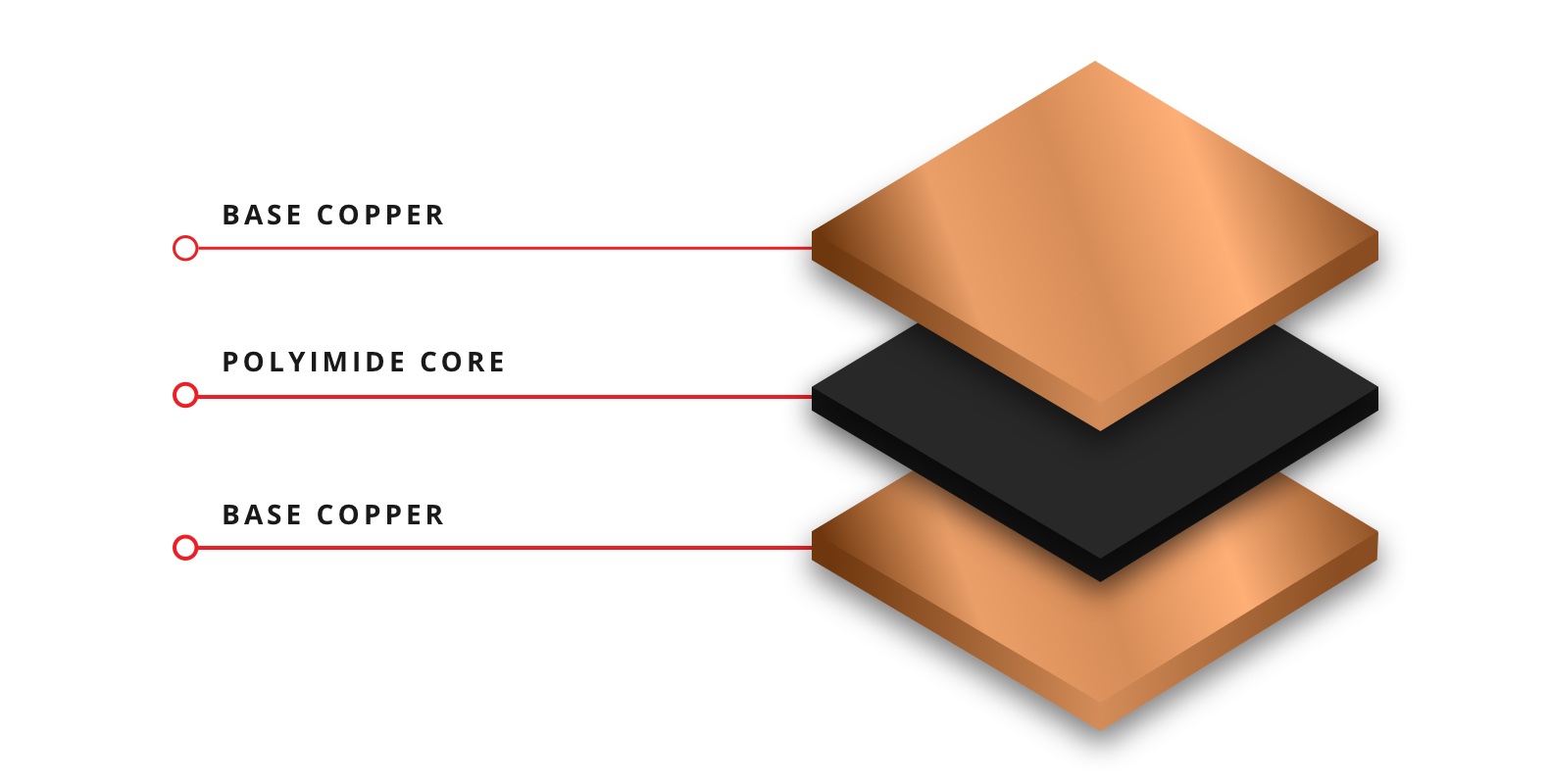
There are two main types of copper used in PCBs — rolled annealed and electro deposited.
Rolled annealed (RA) copper foil begins with melting the copper in a crucible, which is a container that can withstand extremely high temperatures. The copper is poured into a mold to create a rectangular shape before it’s then submerged in cleaning chemicals. (This process is referred to as pickling.) Once all of that is completed, the copper is fed through a press roller until a certain thickness is achieved.
Electro deposited (ED) copper is a less expensive alternative for projects that don’t require a lot of flexibility. ED copper is prone to cracking if the bend radius is too tight. Copper is available in a variety of thicknesses — ¼ ounce, ⅓ ounce, and one ounce. An increase in copper thickness can affect the flexibility of the project, which is why projects tend to have lighter weights (⅓ and ¼ ounces as opposed to ½ and 1 ounce).and even up to 3 oz. There are heavy copper flex PCBs, which contain at least 1-3 ozs. of copper. These PCBs are typically used in higher amperage designs.
A coverlay is a solid layer of polyimide with a layer of adhesive (either acrylic or epoxy-based). It’s a common way to insulate materials that are often preferred due to flexibility and reliability.
A soldermask is applied by a screening process; a coverlay must be drilled and routed, then laminated.
Many flex circuit projects used the DuPont CB028, which is flexible silver shielding. This is a screened-on ink that’s more pliable than a standard copper shield. Though the screened-on ink is thinner and more flexible than copper, it does require an insulator.
Another option is a shielding film from Tatsuta, which contains a conductive adhesive-free material that’s applied to the silver itself in addition to a coverlay insulator.